Creating a Spider Robot
using LEGO-Mindstorms
René Schalburg
mail:recrene@daimi.aau.dk
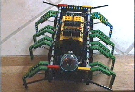
Figure 1: Scaling a doorstep
 |
Abstract:
Trying to create your first legged robot is bound to lead you into a large
number of problems. This paper describes, in fair detail, how such a robot
where constructed by the author. I have tried to give solutions or alternatives
to the problems encountered by me. Also, it have been my purpose to comment
on the Mindstorms setup and its usefulness as a robot construction tool.
It is my hope that I in this way can give others who want to try, a head
start on the process.
List of Figures
Introduction
The CIT started a collaboration project with LEGO, with the purpose of
using their products for robot construction, in January 1998. As a consequence
hereof we obtained a large amount of LEGO bricks from their Technics line,
as well as access to their, yet to be released, LEGO Mindstorms programmable
brick, the RCX. We also obtained access to the LEGO dacta control and sensor
products.
It was part of the deal with LEGO, to use their equipment for robot
building in a one semester course, in the spring of 1998, at the Institute
of Computer Science at Aarhus University. My contribution in this course,
was to build a legged robot.
Forming the idea
In January 98, I participated in a workshop on robots and artificial life.
One of the papers presented there was about simulation of web construction
by common garden spiders. The presentation gave me the idea for this project
namely, to construct a walking insect robot using LEGO and their programmable
brick, the RCX, which is to be used in the Mindstorms construction sets.
Why should I try to build an insect? Well, primary the task of building
a legged robot would be a constructional challenge for me even as a experienced
LEGO user. Secondly I had at that time knowledge of a six-legged gait that
was easy to implement. Finally, a six legged construction was in my mind
easy to balance enough to work. All in all, the goal seemed reasonable
given the limited available time and my construction capabilities.
The hardware
To better understand the design considerations let me first describe the
capabilities of the LEGO hardware.
Technics bricks
I will start to assume that the reader is familiar with the standard LEGO
Technics bricks. I will however say that there are axis of varying length,
various bend and straight joints, gears, toth bars, pull/push rods, and
a lot of other stuff. Please see Figure 2
for a sample of bricks.
Figure 2: Sample of LEGO Technics bricks.
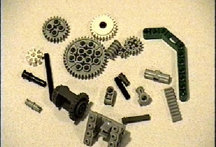 |
I observed only two problems with the bricks: (a) the gears are
all quite loose which makes it harder to use the smaller ones, and some
design afford must be used to make sure that the bricks does not come apart
when th robot is running.
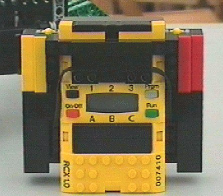
The RCX
The LEGO RCX is an improved and wireless version of the LEGO Control Lab
interface from the LEGO Dacta school set. It is powered by six standard
AA type 1.5V batteries, but can also be supplied with power from a 9V adapter.
It contains a microprocessor with some (> 32K) RAM, an operating system,
an infrared link capable of 2400 baud data transmission, three 10bits A/D
converters, and three 9V analogue outputs. The outputs can be connected
to motors or lights and the A/D converters can be connected to temperature,
touch, angle, or light sensors (standard LEGO items).
The processor comes with a simple Basic-like programming language, and
can work autonomously or be controlled from a PC via the infrared link,
which also functions as a download interface. The link can also be used
for communication between several RCX's in a simple one-byte-at-a-time
manner with only basic error detection.
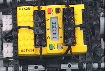
For layout of the RCX, see Figure 3
below.
Figure 3: The LEGO RCX programmable brick
 |
The operating system, is of the multi-threaded type, allowing for up
to 8 simultaneous threads with shared memory slots.
Motors and gears
As mentioned previously, the motors take up to 9V input, which are transformed
in a standard manner into rotation on a normal LEGO axis.
Figure 4: LEGO motors
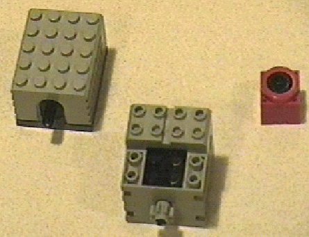 |
There are three types, see Figure 4.
They are, from the left, ungeared (low torque), geared (medium torque),
and the geared mini motor (very low torque). The second is the most useful,
and this is also the only one used by me.
Sensors
There exists four types of sensors in the LEGO line, see Figure 5.
Figure 5: LEGO dacta/Mindstorms sensors
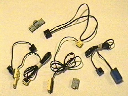 |
-
Light sensors. An active light sensor, measuring visible light level in
a gray-scale manner. The sensors are unfocused and quite hard to interpret,
as they are greatly influenced by the environments general light level.
-
Temperature sensors. A simple resistor based temperature sensor. It is
fairly accurate, giving a 0.1 degree Celsius resolution.
-
Angle sensors. Capable of measuring 1/16'th of a complete revolution. Often
used with gears for more accurate measurements.
-
Touch sensors. Simple on/off switches.
The sensors can be combined on the same input channel, however in that
case the user will have to interpret the input himself instead of using
the supplied input channel modes. But for example light and touch sensors
may be combined enabling the user to measure light when the switch is on
only.
Pneumatics
There exists a pneumatics for the Technics line
as well. It is complete with a pressured air tank, two types of pumps and
pistons, one type of pneumatic switch, flexible tubes, and tube joins.
See Figure 6.
Figure 6: LEGO Technics pneumatic components
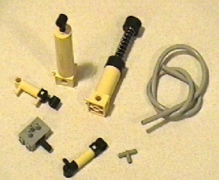 |
To be useful in a robot however, there must be assigned motors for
switches and pressure generation, and for this particular reason they was
disregarded early in the design process.
Implications for design
The main design implication of the RCX module, it that you can only control
three motors with each brick - unless you use one motor to choose, by the
use of some switch or special gear, between several others. In essence
any amount of motors could be controlled, but a lot of construction effort
would have to be used to make things work properly - and you would probably
have to sacrifice one or more of the input channels to obtain safe switching
between motors or motor functions.
Personally, to reduce the mechanical complexity, I have chosen to use
only four motors for the spider. Two of these always working together to
generate enough power to lift the robot on its legs.
The number of inputs, have been no great problem, as I only use two
touch sensors, on the same input channel, to control the walking process.
The remaining two inputs I have used as bumper triggers attached to a large
antenna in each end of the robot, but they could almost as easily have
been used with light sensors to achieve a simple vision system.
Designing the spider
Being a computer scientist, I attacked the design task as I would a program
design task. I chose to create prototypes examining part problems and also
prototypes of the finished product.
Leg design
The legs are off cause a critical design item in any walking robot. It
also turned out to be the most difficult part in the entire process. The
legs on a spider must have at least the following properties:
-
1.
-
Each must have two degrees of freedom, up-down and back-forward.
-
2.
-
The entire leg, i.e. including body fixtures, must be strong enough to
carry (and lift which is harder) up to half the body weight.
-
3.
-
You must be able to transfer enough power to lift half the body weight
to each leg.
The first two properties are quite easy to accommodate with LEGO, the third
however required several experiments and resulted in a solution where the
two central leg pairs are moving together, aiding each other in this way.
For the actual power transferal I choose to use the thin plastic rods
found in some Technics sets.
Other ways to do the lifting could have been
-
To glue part of the assembly together.
-
To use pneumatics.
Gluing was not really an option while I hadn't explored every conceivable
option. To use pneumatics, seemed as a good idea at first. I realized,
by use of a single leg implementation of pneumatics, that I would have
to use a lot of motors (using the same output) and a lot of pneumatic tubes
and pistons, to make a six legged robot walk. I would surly gain speed
and flexibility if I could generate enough pressure with sufficient
speed to make it work at all. In the end the idea was disregarded as impractical,
as it seemed to introduce more weight and need of more space whenever a
problem was solved.
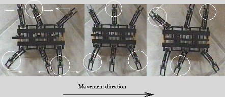
Leg movement
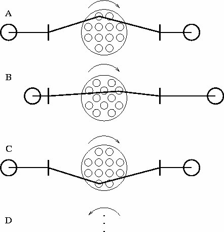
The gait I had decided to use, was a simplified
six-legged insect gait. Figure 7 illustrates
this gait, which consists of a very simple motion pattern.
Figure 7: Gait example - ringed legs are lifted
 |
First prototype
The purpose of the first prototype, was to investigate whether it would
be possible to use springs to do the lifting. If this was possible it would
enable me to reduce the power needed for this purpose as I then could use
some of the power to contract the springs and some for the lifting and
in this way distribute the power. The designed model, see Figure 8,
was however not capable of lifting only very little weight.
Figure 8: First prototype
 |
It did however prove to me that a very stable gait could be developed
with the simple gait described in 4.2
above. The effect of having three widely spread ground contact points were
immediately evident - there would be no tripping with this kind of robot.
Another item this prototype showed me, was that I didn't have to worry
about the leg strength, but a lot about how much weight I would put into
the body.
Second and third prototype
I now had three tasks before me.
-
1.
-
I had to evolve some method of lifting the body/legs.
-
2.
-
I had to evolve a way to control the back-/forward motion of the legs in
each side. This in a way, so I could move the legs on each side independently
of each other.
-
3.
-
I had to program the RCX to control the movement.
Lifting the body
A minor test were done with pneumatics, but as described in 3.5
this was quickly disregarded.
Two other methods were investigated, both using the formerly mentioned
4.1
for power transfer. Chains exists, but as I had to apply real power to
both lifting and lowering of the legs it was better to use something which
allowed for both pushing and pulling.
Rods and large gears
The idea was to fasten the rods, from the same position of both sides of
the robot, together near edge of a large gear. By turning the gear I could
then pull the rod in one side and push the other.
The solution showed to give three problems.
-
1.
-
There was a build in forward and backward motion of the legs, as the rods
are not completely flexible.
-
2.
-
It was hard to control the size of the motion, i.e. how high the legs were
lifted and lowered, because the gear was of limited size, and had only
a few points where fastening was possible.
-
3.
-
Because the rods were fastened on the side of a gear, is was not possible
to ensure it didn't work itself off the gear as the robot moved.
Regrettably I have no pictures of the second prototype using this principle,
but I have tried to make a simple illustration of this principle, see Figure
9.
Figure 9: Prototype 2 - rods and large gears
 |
Tooth-bar for lifting
This idea is probably the most used by LEGO. A small gear are used together
with a "tooth-bar" to generate a side-to-side motion. The method is well
known from e.g. steering the front wheels of a car. One disadvantage of
this method, is that it requires a fairly wide body, if part of the assembly
can't go outside the frame. Also, for the selected gait, I would have to
reverse the direction of the bars movement for the center leg-pair, as
it would have to lift the right side leg when the neighboring right side
legs were lowered. This was done by attaching the tooth-bar on the opposite
side of the lifting axis running in the entire robots length. For pictures
toothbar details, please see Figure 20,
Figure 14, and Figure 15.
Though the third prototype used this principle, there was some problems
with the concept. Attaching the tooth-bar on opposite sides of the lifting
axis was the main cause of a somewhat week design, as it gave a sloppy
fastening of the tooth-bars. The thus generated large movement space, enabled
the rods to work in their mountings, and they would therefore loosen them
self as they were working. The idea was sound enough though - with some
improvements it was also implemented in the final prototype.
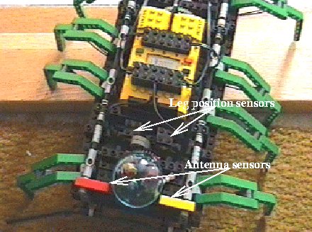
Sensors
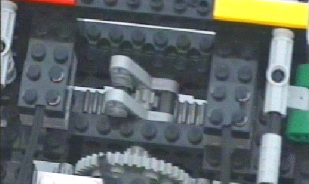
The design with a common lifting axis, required me to know when the legs
were lifted/lowered enough to do the actual back/forward movement of the
legs. For this purpose I mounted a double touch sensor to be activated
by a small rod. This rod was in turn fastened to the lifting axis, and
would thus turn from side to side, much like a wind-screen wiper, and activate
one of the two linked sensors.
There was also mounted sensors attached
to a wide antenna at each end of the body. Each side of the antennae got
a separate set of sensors which enabled me to tell a little about the direction
of obstacles.
Figure 10: Sensors mounted since prototype 2 (final prototype)
 |
Programming the RCX
As the second and third prototypes actually could mount the RCX, it was
also now the time for the programming.
The RCX firmware supports up to eight simultaneous threads or tasks,
why I tried to use a separate thread for each control-task.
The tasks were
-
1.
-
Lifting and lowering of the legs.
-
2.
-
Moving the legs at the left side.
-
3.
-
Moving the legs at the right side.
-
4.
-
Monitoring antenna sensors.
Lifting and lowering
The lifting and lowering of the legs are controlled the following task
begintask lift
  while true do
    reverse(liftmotor)
    start(liftmotor)
    while(liftsensor = true) do wait end
    while(liftsensor = false) do wait end
    stop(liftmotor)
    timevar := 50       ; run movetasks for 5 secs.
    while(timevar > 0) do wait end
  end
endtask
If all the legs starts on the ground the task gives the desired result,
since when it starts it does not matter which legs are lifted and which
are lowered. After lifting/lowering it waits until movement is done and
then reverses the process lifting/lowering the other set of legs.
Moving the legs
Moving the legs are actually done in two tasks, one for each side of the
robot. The moving tasks are described below
begintask move
  while true do
    while(timevar = 0) do wait end
    reverse(mylegmotor)
    start(mytimer)
    start(mylegmotor)
    while(mytimer < timevar) do wait end
    stop(mylegmotor)
    timevar := 0
  end
endtask
The algorithm could be disastrous because there are no checking
of whether the legs are moving too far. The LEGO motors are, however, sufficiently
weak that this does not matter. The drawback are, off cause, that only
limited power could be put into the motion or the model would tear
itself apart.
Obstacle avoidance
As mentioned previously, 6.1.3, there
was antennae mounted in both ends. I created the following task for each
robot side, which at any pressing on of the attached switch would reverse
the direction of the legs on the corresponding side.
begintask antenna
  while true do
    while(myswitch = false) do wait end
    reverse(mylegmotor)
    while(myswitch = true) do wait end
  end
endtask
As the antenna on one side touches an obstacle, the legs on the same side
will immediately reverse their direction. By this the robot starts to move
away, on the assumption that it moved towards before, from the object and
thereby rotating the robot and avoid further contact by the antennae on
that side. By adjusting the length and shape of the antennae, I was guaranteed
(99%) that the antenna would touch again with the other side. In this way
the robot would start to move backwards, now having reversed the leg movement
on both sides.
Final prototype
The final prototype in-cooperated most of my previous findings.
-
Tooth-bars for lifting.
-
Plastic-rods for power transferal.
-
Program structure (actually the entire program).
An extra feature was also included, as I made a remote control for the
robot.
Remote control
The remote control consisted of one RCX with two touch-buttons mounted.
See Figure 11 for a picture.
Figure 11: Remote control for the spider robot
 |
It worked by continuously writing the state of the switches into a variable
on the robot RCX. The RCX part interpreted the switch states as one of
the antenna switches by a variant of the antenna task, 6.5.
begintask robot_remote
  while true do
    while((myid and remote) = false) do wait end
    reverse(mylegmotor)
    while((myid and remote) = true) do wait end
  end
endtask
In this way I didn't have to make other changes to the program, and would
still get the desired effect - remote control.
The remote-control resident task was also quite simple.
begintask remote
  while true do
    state := 0
    if(left_switch = true) then state := state or left_id endif
    if(right_switch = true) then state := state or right_id endif
    write_to_robot(remote,state)
  end
endtask
It simply copies the switches state to a variable and send it to the robot.
Conclusion
The exercise on creating a robot have been ``quite a nice´´
experience. One could argue the usefulness as a computer science exercise,
as most of the work have been done on the physical aspect of the robot.
The argument being that such work is most relevant to engineering sciences.
It is my personal opinion, that the structuring, knowing-the-limits
and step-wise-refinement of the task are very relevant for a computer
scientist, and I therefor anticipate, that I will get long term benefits
from the task in any case.
I believe that my end-product, the Spider Robot, are ``a nice toy´´,
but it could serve as a basis for further studies. Such work might concern
topics as
-
Individual leg control, by use of several RCX or a specialized computer
board.
-
Using neural networks to control, including timing, the movement of legs.
-
Using GA/GP to create control programs.
-
Further improve the lifting and swinging of the legs to get a more versatile
robot.
-
Add vision, sound, or feeling sensors and do exploration.
Off-cause many more could be thought off - and some of the above could
be made with any movable robot, but the spider have at least three advantages
-
1.
-
Being legged, it is not restricted to smooth surfaces.
-
2.
-
The simple control, make it likely that an adequate one could be generated
with NN's or GA's.
-
3.
-
Being spectacular, it is almost certainly more interesting to a spectator,
regardless of capabilities, than a more standard wheeled robot. If show-effect
is beneficial to a project, eg. for funding, the spider could have an advantage.
The first and last of the above, was clearly demonstrated at the '98 Robocup
tournament in Paris. Here the spider got more than its share of attention,
in-spite of the fact that it could do nothing except than moving a little
back and forth, and even though this movement was very slow.
I believe its safe to say that LEGO Mindstorms is a very useful robotics
tool. You will, in an easy way, get powerful construction capabilities,
sensors - though primitive, and a little - but enough - computing power.
Add on to this, that many people, and presumably most roboticist, have
a lot of past experience with LEGO construction, and therefore a natural
understanding of the strengths and limitations of the bricks. All in all
my warm recommendation for LEGO as a robotics tool, but also a piece of
warning; If you want to do something complicated, you almost certainly
need extra computing units to do input/output processing.
René Schalburg, November 2, 1998
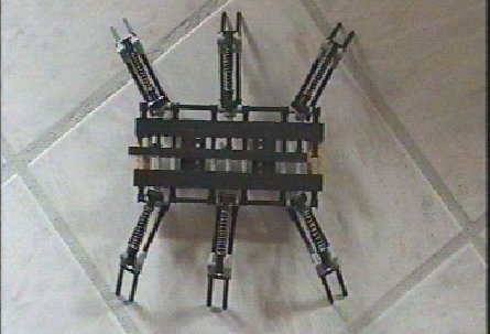
Pictures of the final prototype
Figure 12: Front view
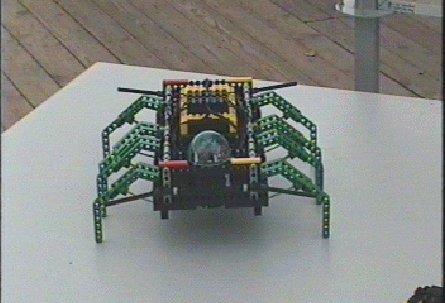 |
Figure 13: Side view
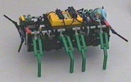 |
Figure 14: Leg detail
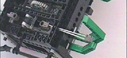 |
Figure 15: Leg detail
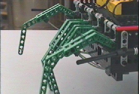 |
Figure 16: Antenna and rear
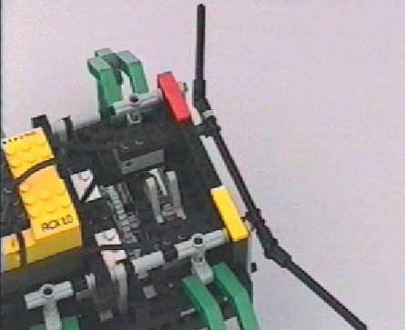 |
Figure 17: Walking
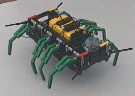 |
Figure 18: Lifting with a tooth-bar, center legs, bottom
view
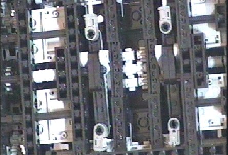 |
Figure 19: Lifting with a tooth-bar, rear legs, bottom
view
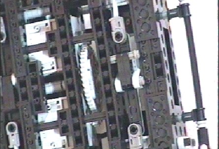 |
Figure 20: Lifting with a tooth-bar, rear legs, top view
 |
About this document ...
Creating a Spider Robot
using LEGO-Mindstorms
This document was generated using the
LaTeX2HTML
translator Version 98.1p1 release (March 2nd, 1998)
Copyright © 1993, 1994, 1995, 1996, 1997,
Nikos
Drakos, Computer Based Learning Unit, University of Leeds.
The command line arguments were:
latex2html -split 0 Spider.
The translation was initiated by Rene Schalburg on 1998-11-02
Rene Schalburg
1998-11-02